
Hi All!
My 2013 1.6L SE came with the 8" MFT display but did not have the factory backup camera option. Therefore, I wanted to add a camera that was low cost, had good night vision, and could integrate into the factory display without spending hundreds of dollars at the dealer. The route I chose was to integrate a setup which replaces the license plate lamp housing. ***UPDATE as of 2020: 4 year review of aftermarket backup camera***
Here is my guide for installing a generic eBay backup camera (described to match '13 and up Ford Escapes) to a 8'' MyFord Touch screen by purchasing an APIM (Accessory Protocol Interface Module) that is compatible- please bear with me as I'm trying to make this as clear as I can by filtering out all of my mishaps to get you all the core directions Please see the attached images for reference to each of these steps.
1) FIND YOUR APIM: I purchased an APIM module on the forum here from another user who was trying to use it his CMAX but it didn't match up for him- This APIM had NAV and the Backup Camera capabilities- you can check this by looking up the VIN of the APIM to see what vehicle it is intended for- The features need to line up, for instance, I don't have the SONY sound package, so if I bought an APIM with the SONY upgrade, it may not work. MY FE has the stock Ford sound package and MFT, but I didn't have anything else. In this post here, I showed how I used another APIM to upgrade my system to have Nav capabilities- http://www.fordescape.org/forum/diy-garage/41362-successful-nav-upgrade-my-2013-fe-se.html Doing the same procedure, I swapped out the APIM (see disassembly and interchanging of APIM in the mentioned link) but this one now had the Backup Camera capability built into it. An easy way to test this is once you have the APIM in, place the car in reverse and wait- after a few seconds it will say "Camera Not Available- Please contact your dealer...blah blah blah". That's just letting you know that it's LOOKING for the camera which obviously isn't installed yet, but this is good to prove if your APIM is configured to accept the component.
2) FIND YOUR CAMERA: Now, the camera I purchased on ebay, is linked here: CCD Car Reverse Camera for Ford Kuga Escape 2013 Auto Rear View Backup Reversing | eBay I did a bit of research and tried to find the best one that I could which wasn't the absolute cheapest, had decent night vision, was a CCD quality component, and then of course had a clean install look so that it could appear SOMEWHAT factory. This means no license plate mount, or anything else that will be dangling in wires when you have to replace your registration tags/plate number, etc... This camera replaces your left license plate light housing, but we'll get to that in a few steps.
3) REMOVE THE HATCH TRIM: Remove the trim on the back hatch. First, start with the handle on the inside. If you take a flat head screwdriver, you can pry off the top cap half of the handle- BE CAREFUL. One side pops free and the other side pivots. Just be gentle and pop it off. (For a demo video on the handle removal, click here) Once you have that off, there will be two philips head screws exposed way down in the cores of the handle- remove them and the other half of the handle will come off as well. This is the subassembly you must remove first in order to remove the main trim panel. Once you're ready and the handle pieces/screws are set aside, firmly and consistently apply pressure around all sides of the main hatch trim panel. One by one, the clips will pop free. Be patient and don't horse it as some of the pop-tabs can b
end and deform. Once you have the main trim panel off, you'll have the three pieces that form the archways and center/top of the hatch. Remove the center first, and then do the corner/arch pieces. They should pop free fairly easily.
4) REMOVE THE EMBLEM TRIM: Now that the trim is removed from the inside of the back hatch, we're going to remove the trim above the license plate where the Ford emblem is- there are four holes main threaded posts and nuts that hold this piece of trim on there. By now since the main trim is all removed, there should be holes in the sheet metal of the hatch that you can look through in the general area of where the emblem trim is located. You should see each of the 4 posts in each of these holes. Use a deep socket to remove the nuts and then there is one snap tab that prevents the trim from falling out- if all four nuts are removed, gently and firmly pull outwards on the trim piece and it should pop free from that one center tab. The subassembly (emblem trim w/wiring for license plate lights) should now be hanging by the wires.
5) INSTALL CAMERA IN PLATE LIGHT HOUSING: Now that the emblem trim subassembly is free and the wires are accessible, swap out the left light housing for the camera housing. Just pull in on the tab and rock the stock housing out of place. The bulb is held in by a turn and lock fashion. Replace the stock housing with the camera / new housing by inserting the bulb and popping the new housing back into the emblem trim. It was my experience that the bulb is fairly loose in the camera/new housing piece, but don't worry, it won't go anywhere.
6) FEED CAMERA WIRES THROUGH RUBBER STOPPER: Since we have the camera installed, we now need to route the wires (red and yellow plugs) through to the inside of the hatch. You'll notice a rubber stopper that's molded around the plate light wires. This is the most snug/best place to have the camera wires go through as well for weather resistance and shock resistance. If you use your fingers or a small pry tool, you can pop that stopper from the sheet metal with the plate wires running right down the center of it. I took a flat razor and sliced right down to the centerline and inserted the wire strands before the yellow and red connectors and then pinched it back together again and pushed it back in place in the sheet metal. Now, your rubber stopper should have the plate light wires AND your camera Video (yellow) and Power (red) wires held in place. You can now re-install the emblem trim by popping it back into the center pop tab, and then put the nuts back on the four threaded posts through the access holes in the inside face of the hatch.
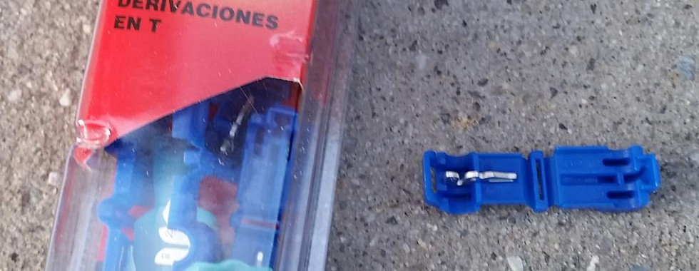
7) TAP YOUR REVERSE LIGHTS: I went to my local auto shop and bought a few boxes of T-Taps. They’re pretty great, but you need to make sure it pierces through the wire housing to actually make contact with the wires. Basically, if you’re not familiar with them, there are two pieces to these taps. First, there’s a piece that folds over the wire and when you squeeze it together with pliers, the metal fitting inside bites through the wire casing and makes contact with the inner strand. There’s then the other half of the T Tap that has a spade connector which crimps around your added/spliced wire and then the spade inserts into the just folded half to make contact with the host wire. BACK TO THE REVERSE LIGHTS. Look at the hatch and locate where the reverse light is located. I went for my back right reverse light bc it’s closer to where the rubber stopper and other wires are. There is another threaded post and nut holding down the assembly. Remove the nut, and then pop the light free. This one was pretty tricky for me because I was trying to pry the light housing off, but didn’t want to scratch the paint. There are a decent amount of snap tabs that hold it in place, but if you’re firm with it, the housing will pop out, exposing the wires for the white reverse lights. I THINK they were green and black. We need to splice into them with the “+” and “-“ Power wires of the camera. This is the included coax connector with dual strand wires which plugs into the RED connector of the camera we just installed. For splicing, I chose to go with the T-taps, so I crimped the primary pieces around the green and black wires with pliers. I then fed the “+” and “-“ wires through the holes in the hatch sheet metal to come through and then crimped the spade T-tap components onto each wire and connected the positive and negative wires respectively. BE SURE NOT TO ROUTE THESE WIRES THROUGH THE HOLE IN THE HATCH WHERE THE THREADED POST MOUNTS TO. I DID THIS AT FIRST AND HAD TO REROUTE IT AS THE POST AND NUT WOULDN’ LEAVE ENOUGH ROOM FOR THE WIRE TO FEED THROUGH. Connect the spade T-Tap with the initial female T-Tap piece that was crimped down with the pliers. Your camera now has a power source. Make sure the wires won’t be inhibited, and reinstall the reverse light housing. Tie down any slack with zip ties.
8) ROUTE THE YELLOW VIDEO CABLE TO THE MYFORD TOUCH DISPLAY: As shown in one of the attached images, I ran the yellow RCA video cable along the existing wiper cable assembly with zip ties and then fed it through the left boot/rubber weather tubing to route it into the cabin. I pulled the cable from between the ceiling material and the roof just to show you how I routed it (see pic). I then proceeded to route it along the left side of the car by popping up the trim as needed to tuck the wiring away from site. I then routed it down along the floor left of the back bench and the driver’s seat and back up behind the OBD port and had the connector hanging in the foot space near the pedals. By now, I realized two problems. A) I didn’t have enough length to make it to the MFT head unit, and B) The MFT wire harness needs two wires be put in place, and the RCA is a coaxial connector. I solved these problems by going to Radioshack and buying a RCA connector with two solder points, one for each positive and negative lead. (Please see pic of the connector with soldered and taped wires.)
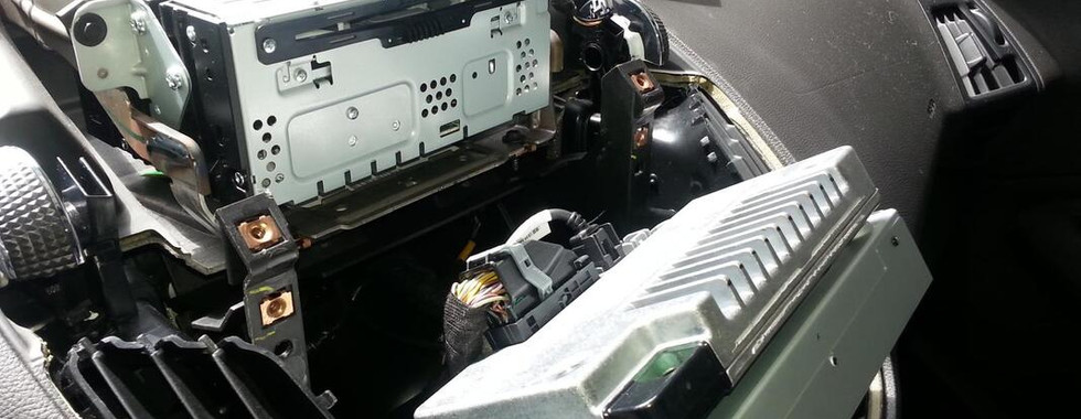
9) FEED AND CONNECT VIDEO “+” and “-“ TO MFT UNIT: Using the RCA connector from Radioshack, I soldered in an extra 36’’ length of wire to each positive and negative post and then wrapped the solder points in electrical tape for insulation (see pic). I also stripped each other end of the wires so that each had 0.5’’ of copper exposed. I then proceeded to disassemble the head unit of the MFT display, starting with the disconnection of the battery and then the consecutive trim pieces (see battery connector pic and linked Nav post up top for full disassembly instructions). Lift out the APIM/MFT screen unit and the side vents so that you can see a gap down to the driver’s footwell to route your wires/ Radioshack RCA connector down to the existing yellow camera RCA connector. I had to use a rod and tape to guide the wires down, but it worked well. I connected the RCA connectors and zip tied it to a bracket that’s out of sight under the steering column near the footwell light. Now, my extension of the Video positive and negative wires with the 0.5’’ stripped ends are exposed and located in the general MFT area.
10) SWAP APIM UNITS: Since you’ve removed the APIM/MFT Screen from the dash, swap out the existing APIM with your new Backup Camera capable APIM in similar fashion to my linked post at the top. It’s just the 4 philips screws holing the screen and APIM together. This is an easy step
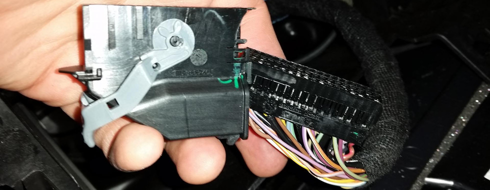
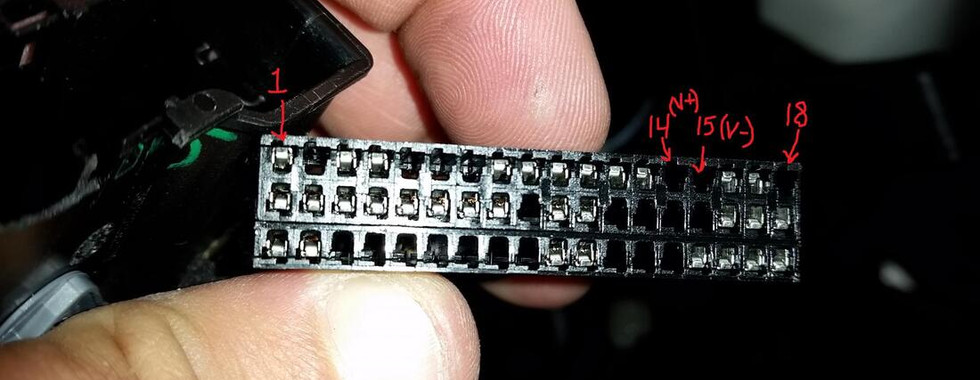
11) INSTALL VIDEO “+” AND “-“ WIRES INTO MFT WIRE HARNESS: This part can be a bit tricky, but I’ll do my best to describe it concisely. IF you look at the main wire harness that goes into the APIM, there’s the gray cam latch and black connector housing. If you look at the side, there are two small and very thin tabs that hold in the three rows of wire ports. I used a small flat head driver and my finger nails to slowly pry these tabs up to slide the actual wire ports from the main housing (see pic of separated housing from ports). You should now be holding the three rows of wire ports with all the wires just inserted into the back. If you look CLOSELY, you can see a “1” and “18” at the top row. There was a gap in my harness where wires 14 and 15 plug in. Wire port 14 is “VIDEO +” and wire port 15 is “VIDEO –“. I took the 0.5’’ of stripped wire lengths and folded them each two times over so that there was a generous thickness of wire core to be inserted into each hole, with the video positive and negative wires going into holes 14 and 15 respectively. Once you make sure that the folded up wires are visible and will surely make contact with the pins of the APIM connector, slide the housing back over the three rows of wire ports until the two thin side tabs snap everything back into place. Your wire harness should APPEAR just as it did when you started, but you’ll now have your camera video “+” and “-“ wires extending from it as well, continuing down through the dash and into the footwell to where the camera video cable is routed in the previous step.
12) PARTIALLY REASSEMBLE THE DASH AND TEST BACKUP CAMERA: Reconnect all wiring of the MFT head unit. This includes the APIM and main wire harnesses, the CD player connector up top, and the sound system interface connector. Loosely place the trim in their correct locations, but don’t screw in the pieces yet- TEST YOUR WIRING. Reconnect the battery and start the car. Put the shifter in reverse, and check your dash to see if the camera shows up. If it still shows the error on the screen for no camera connected, go back and check your wiring. If it works, CONGRATS! Turn off the car and screw the MFT head unit back into place and reinstall the trim pieces properly. Don't forget to put your hatch trim back together as well and remember the order of the upper trim pieces and the handle assembly.
After a very long novel of an explanation, you’re done!!! I hope that wasn’t too painful, but wanted to share the details in hopes that it's helpful.
***PLEASE NOTE*** This camera comes with an extra red wire sheathed in with the yellow video cable. This is a “trigger” wire used in other vehicles but DOES NOT APPLY TO OUR FE’s. Just disregard/ignore it. It was a major source of confusion for me, but we don’t need it.










Comments